___________________________
Breadboards(Solderless one) contains columns of connected sockets for positioning electronic components to create an electric circuit. There two rows along the length of a breadboard. These rows are used to connect to power (red) or ground (blue) lines in the circuit. Each short column of the breadboard are made of holes whicch are connected together. Note that columns are linked together.
Batteries are a commonly used to power breadboards. This approach has some setbacks. Most batteries are not rechargeable. Often times, you have to get rid of it, each time it runs out. For some, especially those who make heavy use of these batteries can be really inconvenient as it can fail you quite often. Given these limitations, one has to consider other options available and this is exactly what this project is all about
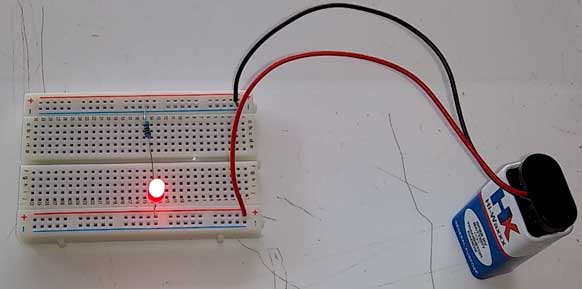
Batteries are readily available. You can either choose a 1.5v and connect them in series using a battery holder or choose a 9v battery and a battery clip to connect it to the breadboard. A great advantage with using a battery is that it is relatively cheap.

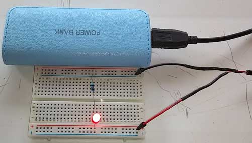
A power bank is little more expensive than the battery we earlier dicussed have this advantage of being rechargeable. You can use it and recharge it when it runs down. Furthermore, it has uses other than powering your breadboard like charging your phone. To connect your power bank to your breadboard, you will need a usb cable adapted to have two jumper wires with pins at the one end. This will enable the usb cable to comfortably fit in the breadboard's holes.

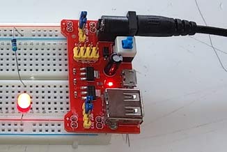
This is my favourite. It fits perfectly on the breadbaord. The Input Voltage is: DC 6.5-12V and provides an Output Voltage of : DC 3.3V and 5V. No need to recharge whatsoever since you will probably connect it to the main supply. You can switch between 5V and 3.3V.

Phone chargers are easy to get and is another cheap option. It will provide an output of around 5V. This is usually enough for most electronics projects. To connect your power bank to your breadboard, you will need a usb cable adapted to have two jumper wires with pins at the one end. This will enable the usb cable to comfortably fit in the breadboard's holes. Since you will connect the phone charger to the main supply, you will have the impression of having an infinite amount of power.
Arduino Uno contains a microcontroller (ATmega328P) to carry out programmed instructions and memory to store data. The power pins allow 5V (5 volts) or 3.3V and ground (GND) to connect to the breadboard and electronic devices. You will need male-to-male jumper wires to connect the arduino to the breadboard.
■ Connect a 470 ohm resistor and a light emitting diode (LED) in series with one leg of the resistor connected to ground line (BLUE) of the breadboard and the positive leg of the LED to the power line (RED) of the breadboard.
■ Connect each of the power supplies mentioned above in turns to the breadboard.
■ Observe how the LED shines as you close the circuit.